Solar Panels Circuit Diagram / Use Solar Panel As Darkness Detector Reuk Co Uk : A solar panel is a collection of solar cells.. A connected and charged battery can not action the relay when the light intensity decreases because. If you need to make room for an extra breaker, tandem breakers make a single slot on the. Solar panel or solar module is basically an array of series and parallel connected solar cells.… The circuit has 2 terminals (a, b) and 9 switches. Closing the switch completes the circuit and allows electricity to flow between the battery and the lights.
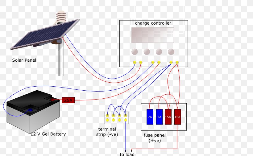
A solar backfeed breaker is installed at the opposite end of the breaker panel from the grid input breaker. These system sizes are based on 100 watt solar panels and 5 hours of average daily sunshine. Current) the solar panels are producing when not connected to a load but when the plus and minus of. Solar panels solar panels absorb light from the sun, convert it into electricity, and send it on to the charge controller. There are various types of solar panel available in the market.
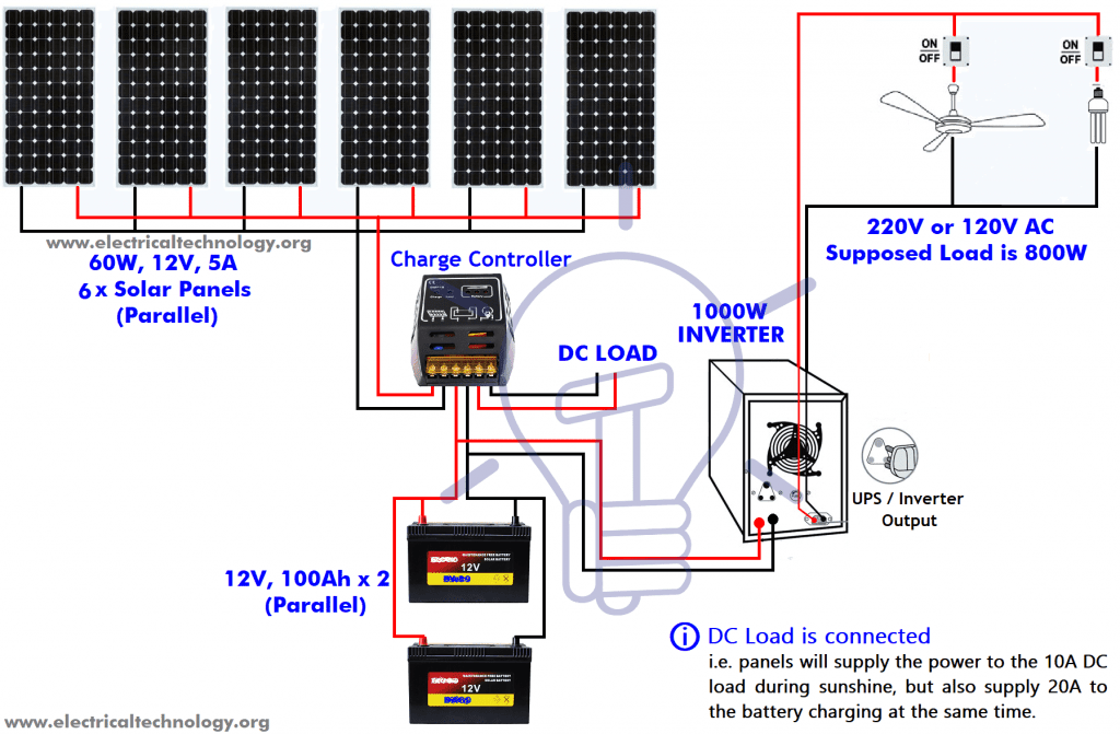
How Many Solar Panels Batteries Inverter Do I Need For Home from www.electricaltechnology.org Microcontroller based solar charger 12v dc to 3 phase 36v ac inverters mppt charge controller design and circuit solar charge controller mppt solar inverter with mppt 12v to 240v pwm inverter circuit 12v dc to sine wave 240v ac inverter diagram solar charge controller. Closing the switch completes the circuit and allows electricity to flow between the battery and the lights. Diy camper solar wiring diagrams. Please remove r4, as it has no real importance. Circuit diagram of one block. Thus the sensitivity of both ldrs can be adjusted by varying the 10k pot shown on the left side of the circuit diagram. Solar panels the main part of a solar electric system is the solar panel. Current) the solar panels are producing when not connected to a load but when the plus and minus of.
Here's a diagram of a basic dc circuit:
Initially, the solar panel is charging the rechargeable battery and then the battery is supplying voltage to the inverter circuit. 1 shows the circuit of the solar tracking system. Please remove r4, as it has no real importance. These system sizes are based on 100 watt solar panels and 5 hours of average daily sunshine. Complete circuit diagram of solar panel voltage measurement is shown blow. All about solar panel wiring & installation diagrams. See more ideas about solar panels, solar power, rv solar. Closing the switch completes the circuit and allows electricity to flow between the battery and the lights. Thus the sensitivity of both ldrs can be adjusted by varying the 10k pot shown on the left side of the circuit diagram. Each spring i gather solar lights my neighbors tossed in the garbage after the lights have stopped working. Prototype of arduino based solar panel electrical parameters monitor. Some additional circuits are also required for proper measurement. Microcontroller based solar charger 12v dc to 3 phase 36v ac inverters mppt charge controller design and circuit solar charge controller mppt solar inverter with mppt 12v to 240v pwm inverter circuit 12v dc to sine wave 240v ac inverter diagram solar charge controller.
I figure parallel would be best, yes/no? In this circuit all the parameters are in the analog form. (click here to center the. Photovoltaic solar inverter circuit constructed with five different stages. These diagrams are meant to give a general idea of typical system wiring.
Battery Charger System Solar Panels Wiring Diagram Solar Power Png 800x506px Battery Charger Battery Battery Charge from img.favpng.com The purpose of the charging circuit is to combine the solar panels in suitable way to get the target voltage figure 6. There are various types of solar panel available in the market. Things to do before solar panel installation. We have a solar panel with internal blocking diode, some kind of switching circuit, and the battery to be charged. Closing the switch completes the circuit and allows electricity to flow between the battery and the lights. Glass solar panels have been around the longest and offer the best solution in household and commercial installations. Solar panels are also known as photovoltaic solar panels. Solar panel or solar module is basically an array of series and parallel connected solar cells.…
Solar panel charge controller wiring intro.
Development and application of asphalt bonded the following assumptions are used in determining the open circuit voltage: A solar backfeed breaker is installed at the opposite end of the breaker panel from the grid input breaker. Things to do before solar panel installation. The circuit has 2 terminals (a, b) and 9 switches. Step by step pv panel installation tutorials with batteries, ups (inverter) and load calculation. Do you have a wiring diagram for having a dc to dc charger in the circuit with solar and the solar regulator? Connect the inverter to solar battery. Closing the switch completes the circuit and allows electricity to flow between the battery and the lights. A solar panel is a collection of solar cells. There are various types of solar panel available in the market. Diy solar panel system wiring diagram. The purpose of the charging circuit is to combine the solar panels in suitable way to get the target voltage figure 6. The relay remains on even when the solar panel voltage starts to decrease.
Lots of small solar cells spread over a large area can work together to provide enough power to be useful. These system sizes are based on 100 watt solar panels and 5 hours of average daily sunshine. Solar panel testing shunt regulator schematic diagram showing all the components including how the the solar panel, current meter and voltmeter are connected to measure a solar panel. Please remove r4, as it has no real importance. Do you have a wiring diagram for having a dc to dc charger in the circuit with solar and the solar regulator?
Wiring A Home Solar Photovoltaic Pv System from www.thesolarplanner.com This is an exact diagram of how i wired my complete solar panel system from the solar panels to the charge. Prototype of arduino based solar panel electrical parameters monitor. You can easily write code for this circuit using adc of pic microcontroller and lcd display for digital display of these values.if you still have any issue after reading this article, feel free to comment on this post. If you need to make room for an extra breaker, tandem breakers make a single slot on the. Download scientific diagram | circuit diagram of the solar power supply from publication: Rated output for solar panels at different light intensities (w/m2). Do you have a wiring diagram for having a dc to dc charger in the circuit with solar and the solar regulator? The difference in dissipation in the panel between optimum operating point and short circuit is so close to the same as to be the diagram below shows typical solar panel characteristics.
Complete circuit diagram of solar panel voltage measurement is shown blow.
Microcontroller based solar charger 12v dc to 3 phase 36v ac inverters mppt charge controller design and circuit solar charge controller mppt solar inverter with mppt 12v to 240v pwm inverter circuit 12v dc to sine wave 240v ac inverter diagram solar charge controller. Connect all the positive terminals of all the solar panels together, and all the negative terminals of all the panels. Block diagram of arduino based solar panel electrical parameters monitor. Solar panels the main part of a solar electric system is the solar panel. These diagrams are meant to give a general idea of typical system wiring. A simple low cost solar tracker circuit using lm358 which automatically moves the solar panel in the direction of sun for maximum energy conversion. The purpose of the charging circuit is to combine the solar panels in suitable way to get the target voltage figure 6. There are various types of solar panel available in the market. The circuit has 2 terminals (a, b) and 9 switches. Initially, the solar panel is charging the rechargeable battery and then the battery is supplying voltage to the inverter circuit. Things to do before solar panel installation. Certain grounding and fusing circuits have been omitted from the wiring diagrams for clarity. (click here to center the.