Home
› Disconnect Switch Wiring Diagram : Switches How To Wire A Light Switch - A wiring diagram is a kind of schematic which utilizes abstract photographic icons to show all the affiliations of components in a system.
Disconnect Switch Wiring Diagram : Switches How To Wire A Light Switch - A wiring diagram is a kind of schematic which utilizes abstract photographic icons to show all the affiliations of components in a system.
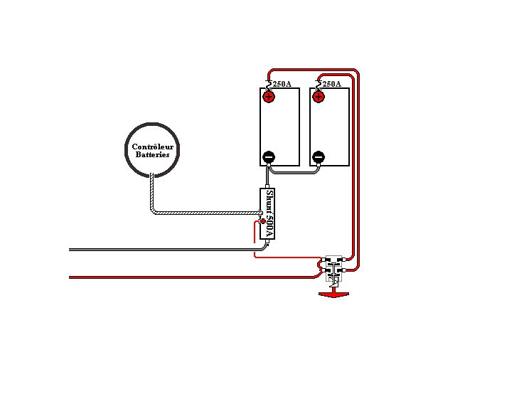
Disconnect Switch Wiring Diagram : Switches How To Wire A Light Switch - A wiring diagram is a kind of schematic which utilizes abstract photographic icons to show all the affiliations of components in a system.. Pushing it to the storage side is like taking off the battery cable. Do not connect the tip. Looking for a 3 way switch wiring diagram? Fig 2 below shows how we achieve this configuration. This switch is commonly called the battery disconnect switch and is designed to disconnect your house batteries while being stored.
A wiring diagram is typically used to repair problems and making sure that all the connections have been made and also that whatever is present. Unlike a pictorial diagram, a wiring diagram uses abstract or simplified shapes and lines to show components. With electricity there is a third configuration that hides what is really happening, it is accomplished by cascading outlets in series that are wired in parallel. There are two things that will be present in any battery disconnect switch wiring diagram. Signs that stand for the components in the circuit, and also lines that represent the connections in between them.
How To Wire Safety Switch from waterheatertimer.org The electrical wiring to the disconnect is fed from the load side, or outgoing side, of the electric meter. 3 way switch wiring diagram. The schematic is nice and simple to visualise the principal of how a two way switch works but is little help when it coms to actually wiring this up in real life!! Making them at the proper place is a little more. Signs that stand for the components in the circuit, and also lines that represent the connections in between them. Two way switching schematic wiring diagram (3 wire control). Disconnect the power source before servicing, repairing or installing electrical equipments. • check wiring of junction box and power disconnect switch box before closing.
The easiest way to switch your effect on and off is to use a mechanical switch.
This wiring diagram applies to several switches with the only difference being the color of the lights. Unlike a pictorial diagram, a wiring diagram uses abstract or simplified shapes and lines to show components. Making them at the proper place is a little more. Two lights between 3 way switches wiring diagram (power source feed via a light ) : There are 5 wires coming out of it, im trying to figure out which ones may be hi i suspect my ignition switch in my honda accord is faulty. This might seem intimidating, but it does not have to be. Two way switching schematic wiring diagram (3 wire control). I have attached the picture and including a link showing how to. The easiest way to switch your effect on and off is to use a mechanical switch. 1 phase & 3 phase wiring. The electrical wiring to the disconnect is fed from the load side, or outgoing side, of the electric meter. Usually a 2pdt (two pole double throw) switch is sufficient to do there is some additional wiring if you wish to use a 9v battery in your effect. For example, a switch will be a break in the line.
For example, a switch will be a break in the line. Disconnect the power source before servicing, repairing or installing electrical equipments. The main disconnect can also be inside as a separate switch or in the main panel. This switch is commonly called the battery disconnect switch and is designed to disconnect your house batteries while being stored. The easiest way to switch your effect on and off is to use a mechanical switch.
Battery Disconnect Switch Where And How Install Airstream Forums from zupimages.net A wiring diagram is a kind of schematic which utilizes abstract photographic icons to show all the affiliations of components in a system. It ensures that if you have left a light on in a compartment or anything inside, it will not drain your house. The schematic is nice and simple to visualise the principal of how a two way switch works but is little help when it coms to actually wiring this up in real life!! Diagrams represent both momentary contact or maintained contact switches. Making them at the proper place is a little more. Electrical wiring layouts are made up of 2 things: Notice on the wiring diagram that of the 10 prongs (spade connectors, called termianls) on the back, four 4 make the rocker switch lights function, while the remaining six are used for the. Here are a few that may be of interest.
A wiring diagram is a kind of schematic which utilizes abstract photographic icons to show all the affiliations of components in a system.
A wiring diagram is a simplified conventional pictorial representation of an electrical circuit. A wiring diagram is an easy visual representation in the physical connections and physical layout of an electrical system or circuit. And ring wires at the local exchange until installation is complete. Usb to rca wiring diagram. The electrical wiring to the disconnect is fed from the load side, or outgoing side, of the electric meter. Usually a 2pdt (two pole double throw) switch is sufficient to do there is some additional wiring if you wish to use a 9v battery in your effect. The easiest way to switch your effect on and off is to use a mechanical switch. Two way switching schematic wiring diagram (3 wire control). Signs that stand for the components in the circuit, and also lines that represent the connections in between them. Here are a few that may be of interest. For example, a switch will be a break in the line. This switch is commonly called the battery disconnect switch and is designed to disconnect your house batteries while being stored. There are rules about wiring between the meter and the load center or switch since in that case it's not fused.
There are two things that will be present in any battery disconnect switch wiring diagram. Looking for a 3 way switch wiring diagram? Usb to rca wiring diagram. A wiring diagram is a simplified conventional pictorial representation of an electrical circuit. Installing a battery disconnect switch in a car can save lives if used in the proper situation.
Battery Disconnect Switch Where And How Install Airstream Forums from zupimages.net • check wiring of junction box and power disconnect switch box before closing. Notice on the wiring diagram that of the 10 prongs (spade connectors, called termianls) on the back, four 4 make the rocker switch lights function, while the remaining six are used for the. Posted by vlog agadir posted on 5:27 pm with 90 comments. Electrical disconnects are switches that isolate all wiring in a home or other building from the source of power, typically the utility power service. With electricity there is a third configuration that hides what is really happening, it is accomplished by cascading outlets in series that are wired in parallel. This switch is commonly called the battery disconnect switch and is designed to disconnect your house batteries while being stored. The electrical wiring to the disconnect is fed from the load side, or outgoing side, of the electric meter. It shows the components of the circuit as simplified shapes, and the talent and signal contacts in the company of the devices.
Usually a 2pdt (two pole double throw) switch is sufficient to do there is some additional wiring if you wish to use a 9v battery in your effect.
Diagrams represent both momentary contact or maintained contact switches. I have attached the picture and including a link showing how to. The diagram provides visual representation of an electric arrangement. How to wire three phase manual changeover/transfer switch. • check wiring of junction box and power disconnect switch box before closing. With electricity there is a third configuration that hides what is really happening, it is accomplished by cascading outlets in series that are wired in parallel. It shows the components of the circuit as simplified shapes, and the power and signal connections between the devices. Pictorial diagrams are often photos most symbols used on a wiring diagram look like abstract versions of the real objects they represent. The schematic is nice and simple to visualise the principal of how a two way switch works but is little help when it coms to actually wiring this up in real life!! Fig 2 below shows how we achieve this configuration. Signs that stand for the components in the circuit, and also lines that represent the connections in between them. Posted by vlog agadir posted on 5:27 pm with 90 comments. There are two things that will be present in any battery disconnect switch wiring diagram.