Home
› Logic Gates Logic Diagram Symbols : Basic logic gates and buffers / A logic gate is a device that can perform one when combined, several gates can make a complex logical evaluation system that has many inputs and outputs.
Logic Gates Logic Diagram Symbols : Basic logic gates and buffers / A logic gate is a device that can perform one when combined, several gates can make a complex logical evaluation system that has many inputs and outputs.
Logic Gates Logic Diagram Symbols : Basic logic gates and buffers / A logic gate is a device that can perform one when combined, several gates can make a complex logical evaluation system that has many inputs and outputs.. Logic gates are considered to be the basics of boolean logic. These logic gates have 3 or more inputs and an output. Logic gate circuits are most frequently symbolized with a schematic diagram through their own exclusive symbols instead of their essential resistors and transistors. In this post on study of logic gates, you will be getting to know complete details on logic gates (electric gates), logic gate symbols, logic diagram and truth tables. What is meant by logic gate?
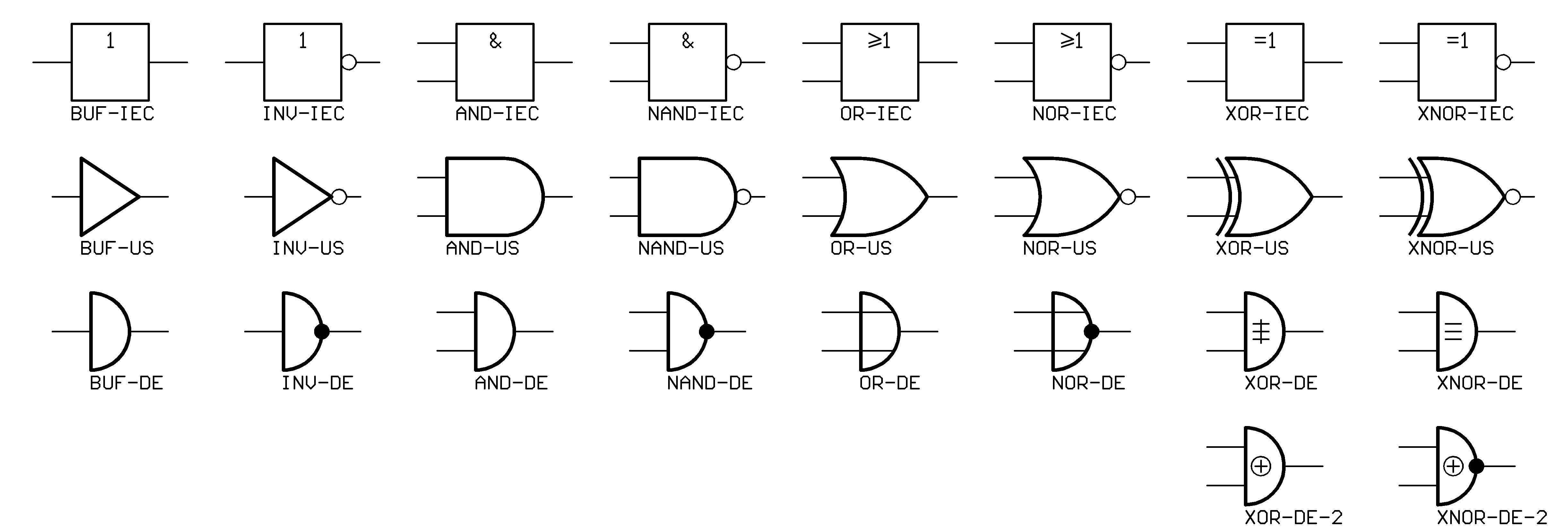
These are part of the building blocks for many other electronic logic symbols. The picture below is a logic gate. It can also be done using nor logic gates in the same way. Each animated diagram shows the input and output conditions for one of the seven logic functions in its two input form. Usually, a logic gate symbol has input on the left and output on the right as shown in the diagrams below.
Contacts and Coils in PLC Ladder Logic | PLC Training | PLC Tutorials from instrumentationtools.com It has n input (n >= 2) and one output. The picture below is a logic gate. Logic diagrams have many uses. This page is a directory for matching symbols for logic gates. We'll discuss some important derived logic gates here. Logic gates are very important and they serve as the building blocks to digital not gates or inverters have a single bit input and a single bit of output. Logic gates definitions, types, symbols and truth tables are discussed. This article explains the basic logic gates like not gate, and gate, or gate, nand gate, nor gate, exor gate and exnor gate with their corresponding truth tables and circuit symbols.
Logic gates are primarily implemented electronically using diodes or transistors.
Logic gate circuits are most frequently symbolized with a schematic diagram through their own exclusive symbols instead of their essential resistors and transistors. Logic gates are the digital circuits capable of performing a particular logic function. Each animated diagram shows the input and output conditions for one of the seven logic functions in its two input form. The first input is for the choice and the next inputs are for the choices. It has one or more input symbols for logic gates. Amplifiers (denoted by triangle shapes) increase the output signal in. A logic gate is a device that can perform one when combined, several gates can make a complex logical evaluation system that has many inputs and outputs. What is meant by logic gate? A logic gate is a switching circuit made up of a combination of transistor switches. Logic gates as switching circuits. Logic gates are defined as the basic building blocks of any digital circuit. Logic gate symbols (digital electronics). In this post on study of logic gates, you will be getting to know complete details on logic gates (electric gates), logic gate symbols, logic diagram and truth tables.
Pls subscribe to this channel for future tutorials (especially on. A logic gate is a small transistor circuit, basically a type of amplifier, which is implemented in different forms within an integrated circuit. Then, we can directly convert the expression into a diagram of logic gates. Logic gate circuits are most frequently symbolized with a schematic diagram through their own exclusive symbols instead of their essential resistors and transistors. The diagrams below show two ways that the nand logic gate can be configured to produce a not gate.
File:Logic-gate-index.png - Wikimedia Commons from upload.wikimedia.org This article explains the basic logic gates like not gate, and gate, or gate, nand gate, nor gate, exor gate and exnor gate with their corresponding truth tables and circuit symbols. Logic shapes like and gate, or gate, not gate and more are included here. Each animated diagram shows the input and output conditions for one of the seven logic functions in its two input form. This page is a directory for matching symbols for logic gates. The outputs of all nand gates are high if any of the inputs are low. Between the logic gate not (a triangle then a circle) and the other symbol (a circle then a triangle) which is located in the right of the clock10. The picture below is a logic gate. Logic gates definitions, types, symbols and truth tables are discussed.
A logic gate is a switching circuit made up of a combination of transistor switches.
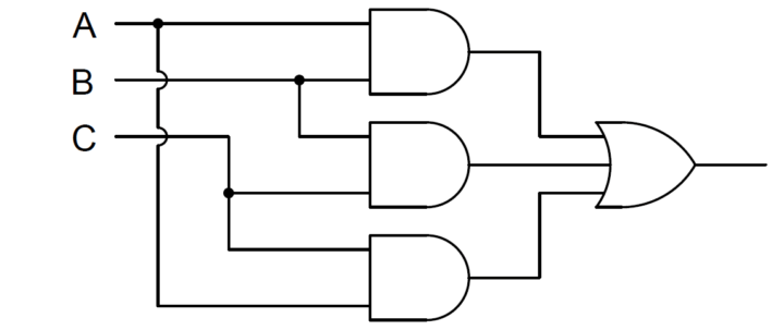
Logic gate symbols (digital electronics). A logic gate performs a logical operation on one or more logic inputs and produces a single logic output. The diagrams below show two ways that the nand logic gate can be configured to produce a not gate. Logic gates as switching circuits. All images should be svg. It has n input (n >= 2) and one output. Translate the the following logical expression into both a truth table and a logic diagram. For ib use the operaor enclosed within a circle. It has one or more input symbols for logic gates. Every logic gate has a graphical representation or symbol associated with it. Logic diagrams have many uses. From transistors to logic gates, you'll find icons that are modeled to international standards. A logic gate is a switching circuit made up of a combination of transistor switches.
A logic gate is a device that can perform one when combined, several gates can make a complex logical evaluation system that has many inputs and outputs. Each animated diagram shows the input and output conditions for one of the seven logic functions in its two input form. Only add images here if they match the images here already. Some types of gate however, are also available. A circuit that works based on the logical decision and the process is called as logic gates.
邏輯圖工具 from cdn-images.visual-paradigm.com Visual reprenstation of logic gates. Every logic gate has a graphical representation or symbol associated with it. This article explains the basic logic gates like not gate, and gate, or gate, nand gate, nor gate, exor gate and exnor gate with their corresponding truth tables and circuit symbols. Most logic gates take an input of two binary values, and output a single value of a 1 or 0. Logic gates as switching circuits. Then, we can directly convert the expression into a diagram of logic gates. A logic gate can be represented by a block diagram as shown in figure. Logic gates are primarily implemented electronically using diodes or transistors.
In practice, each logic gate is represented by a.
It has n input (n >= 2) and one output. A logic gate is a small transistor circuit, basically a type of amplifier, which is implemented in different forms within an integrated circuit. Pls subscribe to this channel for future tutorials (especially on. Derived logic gates are formed from the combination of two or more of the primary logic gates. Logic gates are symbols that can directly replace an expression in boolean arithmetic. Logic gates are the digital circuits capable of performing a particular logic function. This is a diagram of a yes gate symbol is without the circle indicates negation y its true table results are opposited to not gate. From transistors to logic gates, you'll find icons that are modeled to international standards. The diagrams below show two ways that the nand logic gate can be configured to produce a not gate. These are part of the building blocks for many other electronic logic symbols. A logic gate performs a logical operation on one or more logic inputs and produces a single logic output. This page is a directory for matching symbols for logic gates. The logic normally performed is boolean logic and is most commonly found in digital circuits.